+34 688 712 866


Description
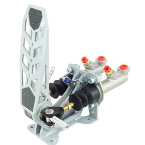
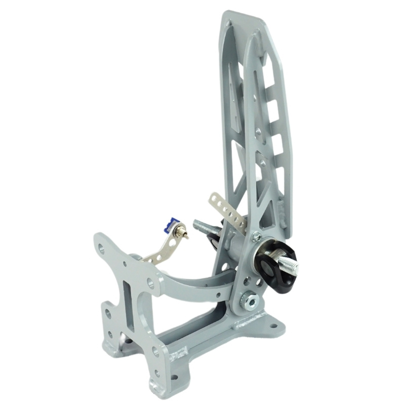
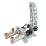
-Brake pedal with 2 independent master cylinders and a balance bar, to regulate the front and rear braking. (Rule T 6.1.2)
-Each hydraulic master cylinder could have its own fluid reservoir. (Rule T 6.1.2)
-The Brake Pedal is designed to resist a force of 2kN without failure. (Rule T 6.1.9)
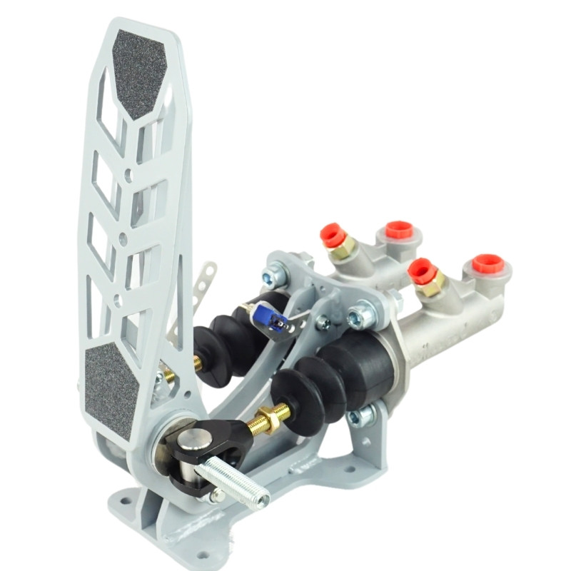
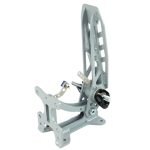
-The pedal is manufactured with steel welded parts, with a lightweight design to improve the stiffness – weight ratio. (Rule T 6.1.10)
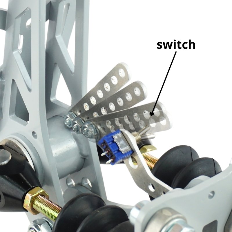
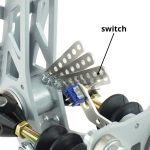
–Brake overtravel switch included. (Rule T 6.2: Brake Over-Travel Switch (BOTS))
-The pedals have a wide surface to improve the driving and ease the pedals combinations.
-The balance bar (included with the pedal) is 7/16”- 20 UNF thread to provide the maximum stiffness. The master cylinders connections are 5/16”- 24 UNF, for Wilwood or Girling master cylinders.
-The pedal ratio is 5:1.
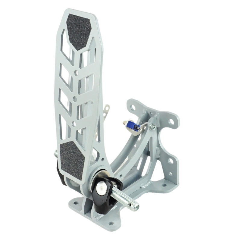
-Possibility to assemble Brake remote adjuster (7/16 UNF) (ref. RPBAB03) to control the brake balance from the cockpit.
-Possibility to install Brake Light switch banjo 3/8 UNF (ref. RPBAB12) in the master cylinder, for the brake light. (Rule T 6.3)
-Possibility to install the Fluid reservoirs (ref. RPBAD02) directly in the master cylinders, or independently.
-The weight of the pedal is 1,4 kg without master cylinders and 2,2 kg with master cylinders.
–Pedal setting is made on the cabin floor with four 6mm metric screws.
-The pedal has anti-slip surface.
-Master cylinders are sold separately.
-All the components have anticorrosion coating to allow the maximum durability.